

 導入
導入 仕様テーブル
 ダウンロード
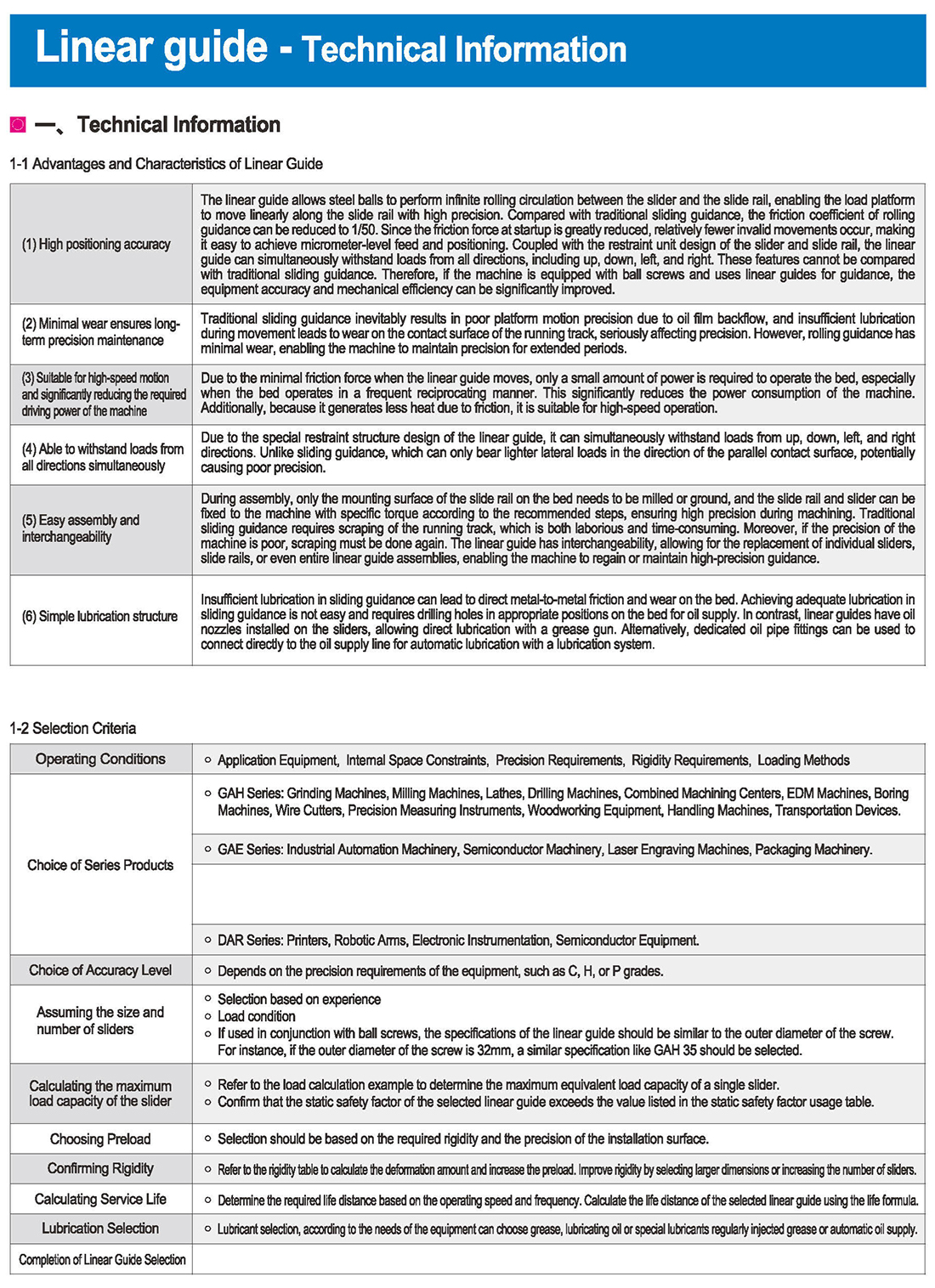
(1)高い位置決め精度
リニアガイドにより、スライダとスライドレールの間を鋼球が無限に回転循環し、荷重プラットフォームがスライドレールに沿って高精度に直線的に移動することができます。従来の摺動誘導と比較して、転がり誘導の摩擦係数を1/50に低減できます。始動時の摩擦力が大幅に低減されるため、無効な動きが比較的少なく、マイクロメートルレベルの送りと位置決めが容易に実現できます。スライダとスライドレールの拘束ユニット設計と組み合わせることで、上下左右を含むあらゆる方向からの荷重に同時に耐えることができます。これらの特徴は、従来のスライディングガイダンスと比較することはできません。したがって、機械にボールねじが装備され、ガイドにリニアガイドを使用すると、設備の精度と機械効率を大幅に向上させることができます
(2)摩耗が少ないため、長期間の精密メンテナンスが可能です
従来のスライドガイダンスは、必然的に油膜の逆流によるプラットフォームの動きの精度が低下し、移動中の不十分な潤滑は、走行トラックの接触面に摩耗をもたらし、精度に深刻な影響を与えます。しかし、転がり誘導の摩耗が少ないため、長期間にわたって精度を維持することができます。
(3)高速動作に適しており、機械に必要な駆動力を大幅に低減します
リニアガイド移動時の摩擦力が小さいため、ベッドの動作に必要な電力はわずかであり、特に頻繁に往復する場合には必要とされる電力は少ない。これにより、機械の消費電力が大幅に削減されます。また、摩擦による発熱が少ないため、高速運転に適しています。
(4)全方向の荷重に同時に耐えることができます
リニアガイドの特殊拘束構造設計により、上下左右の荷重に同時に耐えることができます。スライディングガイダンスとは異なり、平行接触面方向のより軽い横方向の荷重しか耐えられず、精度が低下する可能性があります。
(5)組み立てやすく、互換性があります
組立時には、ベッド上の摺動レールの取付面を粉砕または粉砕するだけで、摺動レールとスライダを推奨ステップに応じて特定のトルクで機械に固定することができ、加工時の高精度を確保します。従来のスライディングガイダンスでは、ランニングトラックを削る必要があり、労力と時間がかかります。また、機械の精度が悪い場合は、再度削り直す必要があります。リニアガイドは互換性があり、個々のスライダ、スライドレール、またはリニアガイドアセンブリ全体を交換することができ、機械が高精度のガイダンスを復元または維持することができます。
(6)簡単な潤滑構造
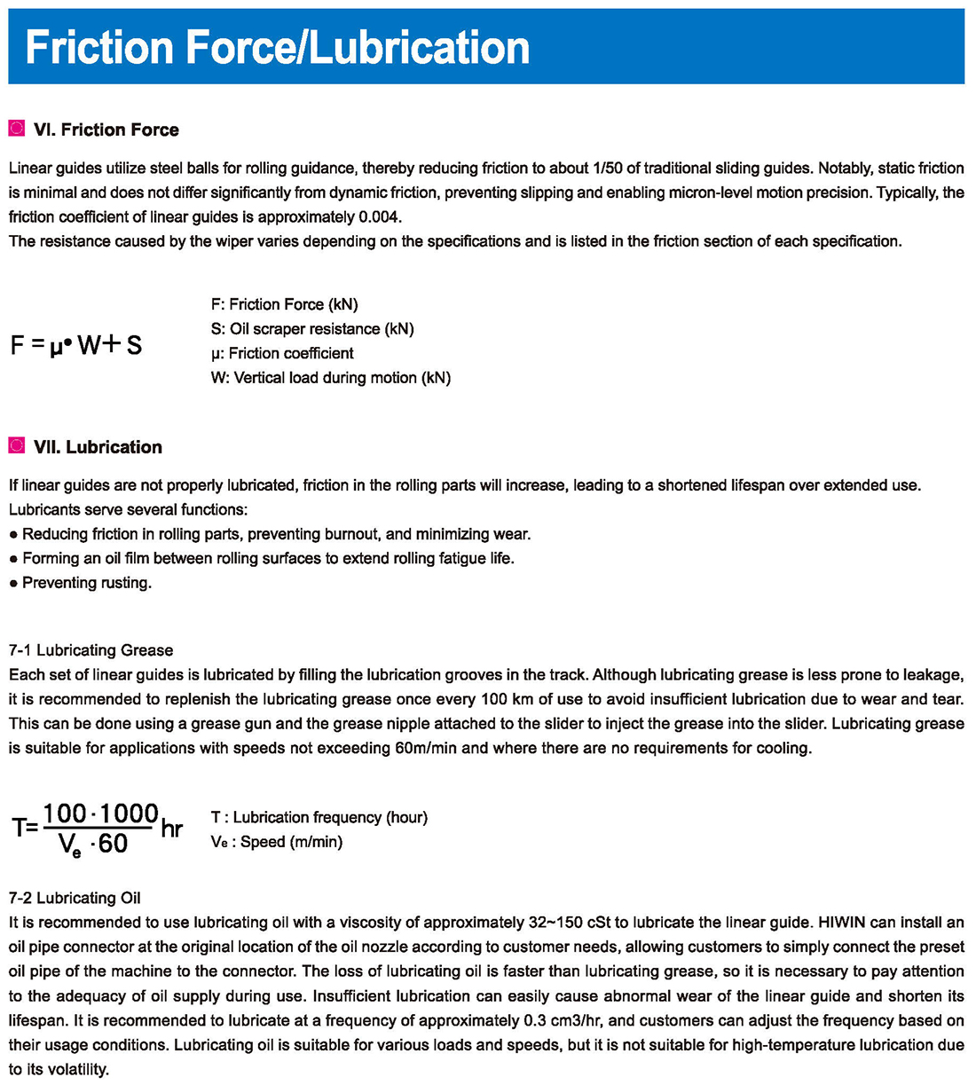
摺動ガイダンスの潤滑不足は、ベッド上の金属間の直接摩擦や摩耗につながる可能性があります。スライディングガイダンスで十分な潤滑を実現することは容易ではなく、石油供給のためにベッドの適切な位置に穴を開ける必要があります。一方、リニアガイドでは、スライダにオイルノズルが取り付けられているため、グリースガンで直接潤滑することができます。または、専用のオイルパイプ継手を使用してオイル供給ラインに直接接続し、給油システムによる自動給油を行うこともできます。 。
。
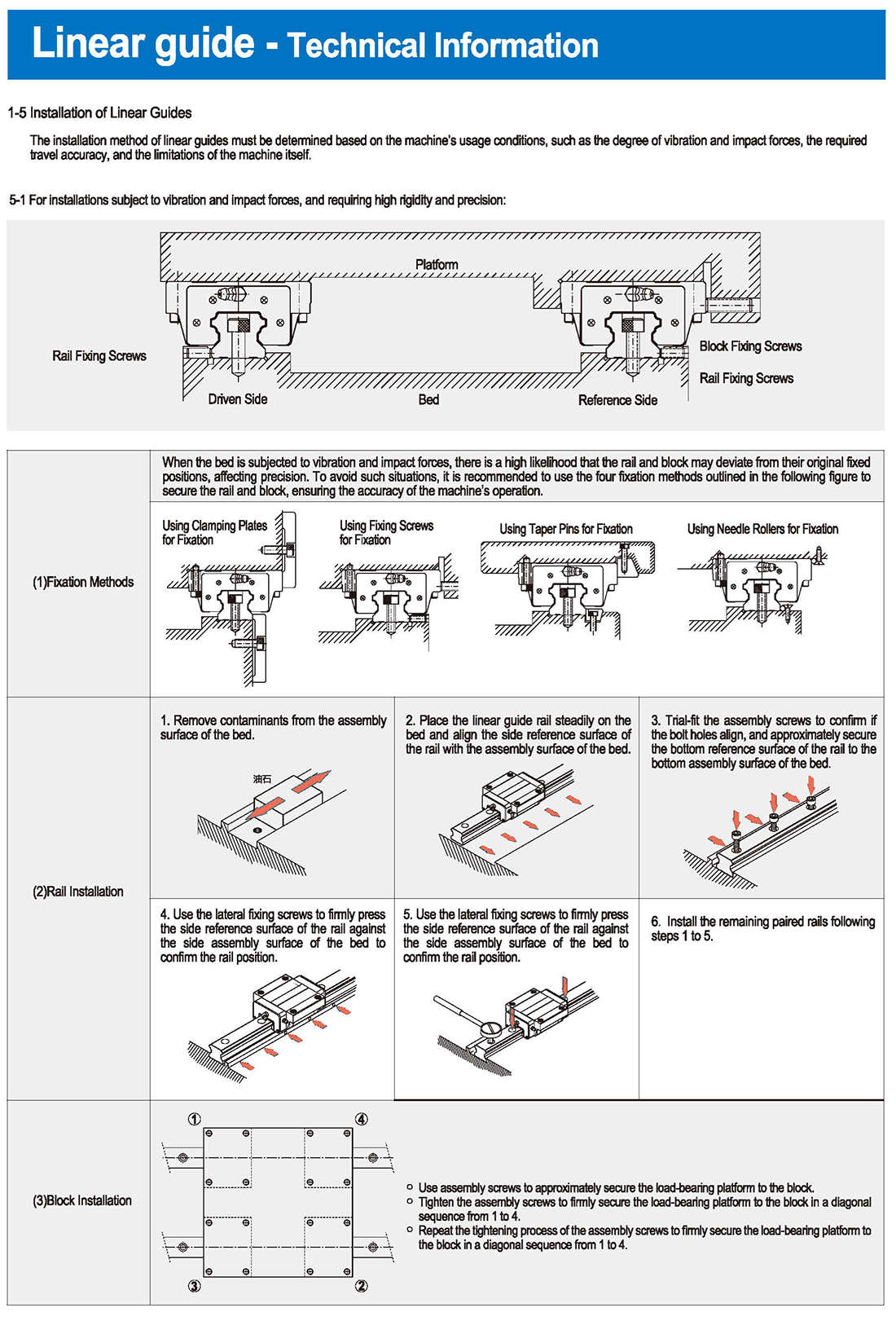


5 Installation of Linear Guides
The installation method of linear guides must be determined based on the machine’s usage conditions, such as the degree of vibration and impact forces, the required travel accuracy, and the limitations of the machine itself.
5-1 For installations subject to vibration and impact forces, and requiring high rigidity and precision:
Rail Fixing Screws Driven Side Platform Bed Reference Side Block Fixing Screws Rail Fixing Screws
Fixation Methods
When the bed is subjected to vibration and impact forces, there is a high likelihood that the rail and block may deviate from their original fixed positions, affecting precision. To avoid such situations, it is recommended to use the four fixation methods outlined in the following figure to secure the rail and block, ensuring the accuracy of the machine’s operation.
Using Clamping Plates for Fixation Using Fixing Screws for Fixation Using Taper Pins for Fixation Using Needle Rollers for Fixation
Rail Installation
Remove contaminants from the assembly surface of the bed.
1 Place the linear guide rail steadily on the bed and align the side reference surface of the rail with the assembly surface of the bed.
2 Trial-fit the assembly screws to confirm if the bolt holes align, and approximately secure the bottom reference surface of the rail to the bottom assembly surface of the bed.
3 Use the lateral fixing screws to firmly press the side reference surface of the rail against the side assembly surface of the bed to confirm the rail position.
4 Using a torque wrench, tighten the assembly screws in sequence with a specific torque to firmly press the bottom reference surface of the rail against the bottom assembly surface of the bed.
5 Install the remaining paired rails following steps 1 to 5.
Block Installation
Use assembly screws to approximately secure the load-bearing platform to the block.
Tighten the assembly screws to firmly secure the load-bearing platform to the block in a diagonal sequence from 1 to 4.
Repeat the tightening process of the assembly screws to firmly secure the load-bearing platform to the block in a diagonal sequence from 1 to 4.

| 分類 | タイトル | ダウンロード |
|---|---|---|
| fa産業自動化ワンストップサービスプラットフォーム |

やあ!おかえり。
お元気ですか?
 英語
英語 ロシア
ロシア スペイン
スペイン イタリア
イタリア アラビア語
アラビア語 韓国
韓国 ドイツ
ドイツ 日本
日本 ベトナム
ベトナム トルコ
トルコ